
Our fleet of over 200 locations comprises various generations of servers and routers. And with the ever changing landscape of services and computing demands, it’s imperative that we manage power in our data centers right. This blog is a brief Electrical Engineering 101 session going over specifically how power distribution units (PDU) work, along with some good practices on how we use them. It appears to me that we could all use a bit more knowledge on this topic, and more love and appreciation of something that’s critical but usually taken for granted, like hot showers and opposable thumbs.
A PDU is a device used in data centers to distribute power to multiple rack-mounted machines. It’s an industrial grade power strip typically designed to power an average consumption of about seven US households. Advanced models have monitoring features and can be accessed via SSH or webGUI to turn on and off power outlets. How we choose a PDU depends on what country the data center is and what it provides in terms of voltage, phase, and plug type.
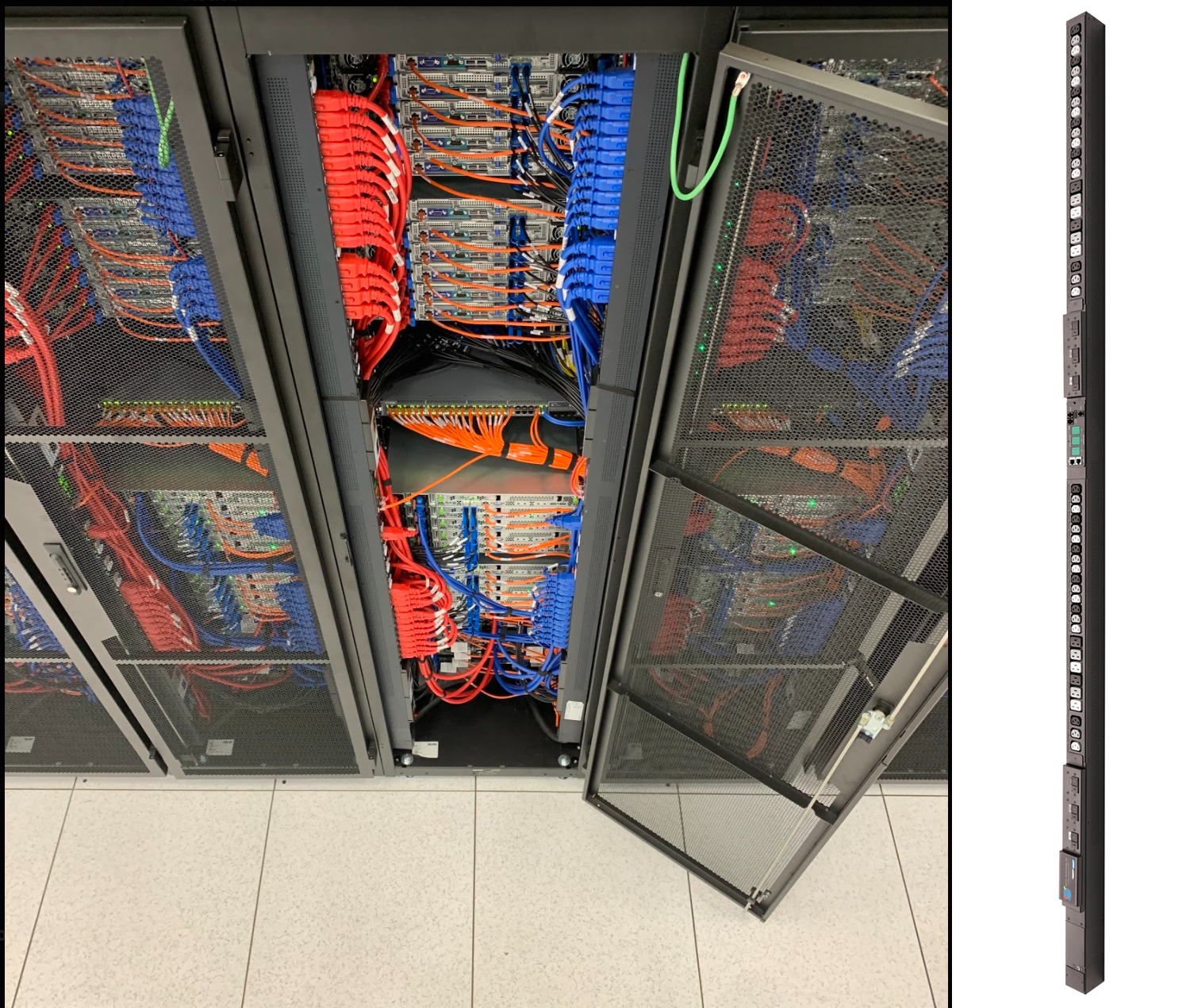
For each of our racks, all of our dual power-supply (PSU) servers are cabled to one of the two vertically mounted PDUs. As shown in the picture above, one PDU feeds a server’s PSU via a red cable, and the other PDU feeds that server’s other PSU via a blue cable. This is to ensure we have power redundancy maximizing our service uptime; in case one of the PDUs or server PSUs fail, the redundant power feed will be available keeping the server alive.
Faraday’s Law and Ohm’s Law
Like most high-voltage applications, PDUs and servers are designed to use AC power. Meaning voltage and current aren’t constant — they’re sine waves with magnitudes that can alternate between positive and negative at a certain frequency. For example, a voltage feed of 100V is not constantly at 100V, but it bounces between 100V and -100V like a sine wave. One complete sine wave cycle is one phase of 360 degrees, and running at 50Hz means there are 50 cycles per second.
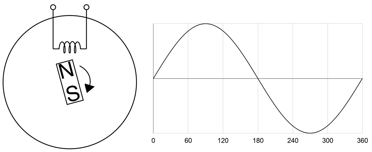
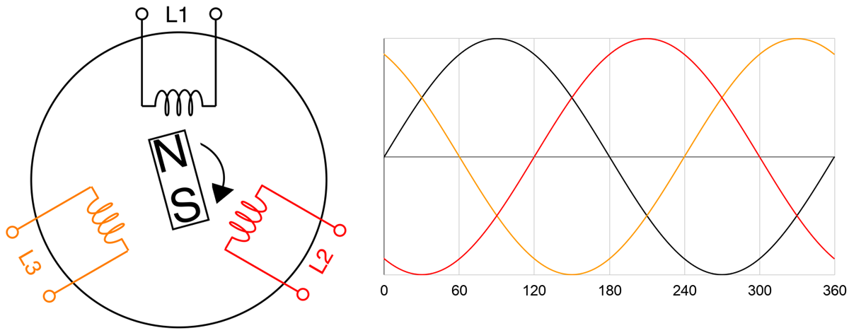
The sine wave can be explained by Faraday’s Law and by looking at how an AC power generator works. Faraday’s Law tells us that a current is induced to flow due to a changing magnetic field. Below illustrates a simple generator with a permanent magnet rotating at constant speed and a coil coming in contact with the magnet’s magnetic field. Magnetic force is strongest at the North and South ends of the magnet. So as it rotates on itself near the coil, current flow fluctuates in the coil. One complete rotation of the magnet represents one phase. As the North end approaches the coil, current increases from zero. Once the North end leaves, current decreases to zero. The South end in turn approaches, now the current “increases” in the opposite direction. And finishing the phase, the South end leaves returning the current back to zero. Current alternates its direction at every half cycle, hence the naming of Alternating Current.
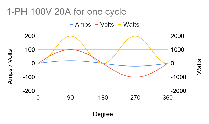
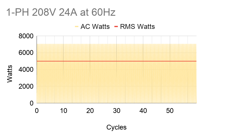
Current and voltage in AC power fluctuate in-phase, or “in tandem”, with each other. So by Ohm's Law of Power = Voltage x Current, power will always be positive. Notice on the graph below that AC power (Watts) has two peaks per cycle. But for practical purposes, we'd like to use a constant power value. We do that by interpreting AC power into "DC" power using root-mean-square (RMS) averaging, which takes the max value and divides it by √2. For example, in the US, our conditions are 208V 24A at 60Hz. When we look at spec sheets, all of these values can be assumed as RMS'd into their constant DC equivalent values. When we say we're fully utilizing a PDU's max capacity of 5kW, it actually means that the power consumption of our machines bounces between 0 and 7.1kW (5kW x √2).
It’s also critical to figure out the sum of power our servers will need in a rack so that it falls under the PDU’s design max power capacity. For our US example, a PDU is typically 5kW (208 volts x 24 amps); therefore, we're budgeting 5kW and fit as many machines as we can under that. If we need more machines and the total sum power goes above 5kW, we'd need to provision another power source. That would lead to possibly another set of PDUs and racks that we may not fully use depending on demand; e.g. more underutilized costs. All we can do is abide by P = V x I.
However there is a way we can increase the max power capacity economically — 3-phase PDU. Compared to single phase, its max capacity is √3 or 1.7 times higher. A 3-phase PDU of the same US specs above has a capacity of 8.6kW (5kW x √3), allowing us to power more machines under the same source. Using a 3-phase setup might mean it has thicker cables and bigger plug; but despite being more expensive than a 1-phase, its value is higher compared to two 1-phase rack setups for these reasons:
- It’s more cost-effective, because there are fewer hardware resources to buy
- Say the computing demand adds up to 215kW of hardware, we would need 25 3-phase racks compared to 43 1-phase racks.
- Each rack needs two PDUs for power redundancy. Using the example above, we would need 50 3-phase PDUs compared to 86 1-phase PDUs to power 215kW worth of hardware.
- That also means a smaller rack footprint and fewer power sources provided and charged by the data center, saving us up to √3 or 1.7 times in opex.
- It’s more resilient, because there are more circuit breakers in a 3-phase PDU — one more than in a 1-phase. For example, a 48-outlet PDU that is 1-phase would be split into two circuits of 24 outlets. While a 3-phase one would be split into 3 circuits of 16 outlets. If a breaker tripped, we’d lose 16 outlets using a 3-phase PDU instead of 24.
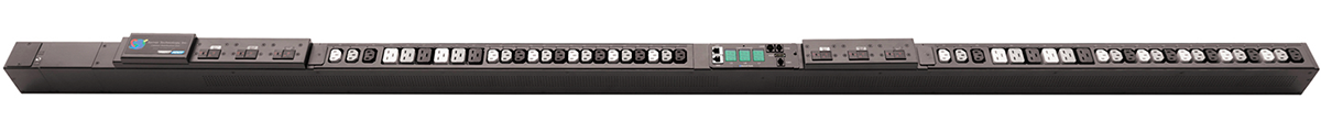
The PDU shown above is a 3-phase model of 48 outlets. We can see three pairs of circuit breakers for the three branches that are intertwined with each other — white, grey, and black. Industry demands today pressure engineers to maximize compute performance and minimize physical footprint, making the 3-phase PDU a widely-used part of operating a data center.
What is 3-phase?
A 3-phase AC generator has three coils instead of one where the coils are 120 degrees apart inside the cylindrical core, as shown in the figure below. Just like the 1-phase generator, current flow is induced by the rotation of the magnet thus creating power from each coil sequentially at every one-third of the magnet’s rotation cycle. In other words, we’re generating three 1-phase power offset by 120 degrees.
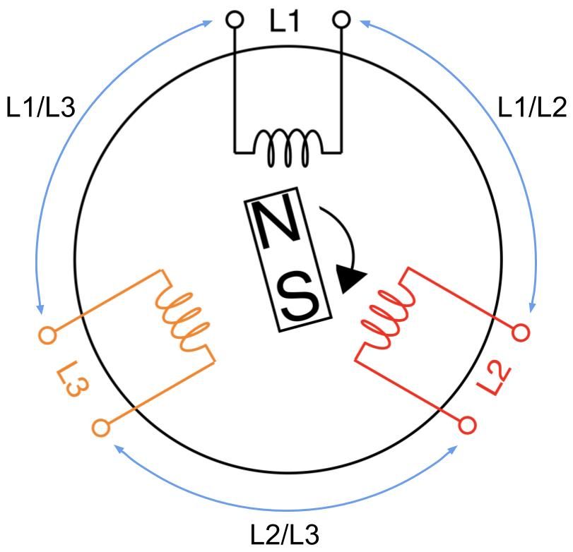
A 3-phase feed is set up by joining any of its three coils into line pairs. L1, L2, and L3 coils are live wires with each on their own phase carrying their own phase voltage and phase current. Two phases joining together form one line carrying a common line voltage and line current. L1 and L2 phase voltages create the L1/L2 line voltage. L2 and L3 phase voltages create the L2/L3 line voltage. L1 and L3 phase voltages create the L1/L3 line voltage.
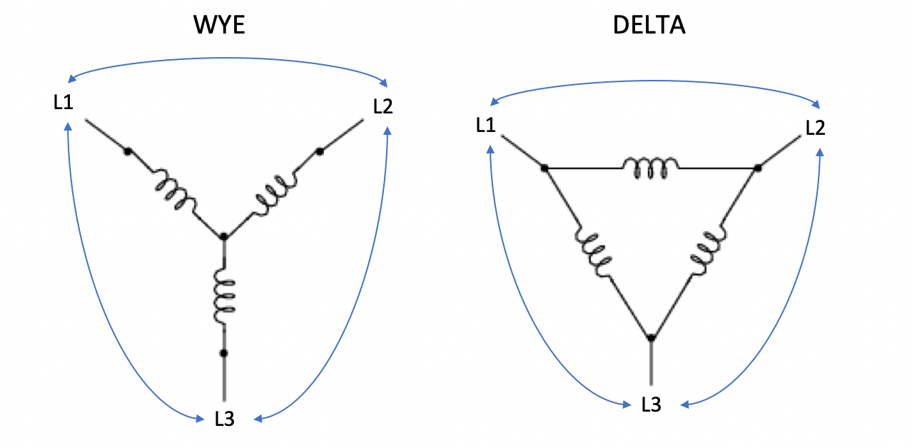
Let’s take a moment to clarify the terminology. Some other sources may refer to line voltage (or current) as line-to-line or phase-to-phase voltage (or current). It can get confusing, because line voltage is the same as phase voltage in 1-phase circuits, as there’s only one phase. Also, the magnitude of the line voltage is equal to the magnitude of the phase voltage in 3-phase Delta circuits, while the magnitude of the line current is equal to the magnitude of the phase current in 3-phase Wye circuits.
Conversely, the line current equals to phase current times √3 in Delta circuits. In Wye circuits, the line voltage equals to phase voltage times √3.
In Delta circuits:
Vline = Vphase
Iline = √3 x Iphase
In Wye circuits:
Vline = √3 x Vphase
Iline = Iphase
Delta and Wye circuits are the two methods that three wires can join together. This happens both at the power source with three coils and at the PDU end with three branches of outlets. Note that the generator and the PDU don’t need to match each other’s circuit types.
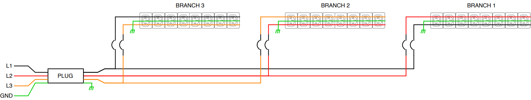
On PDUs, these phases join when we plug servers into the outlets. So we conceptually use the wirings of coils above and replace them with resistors to represent servers. Below is a simplified wiring diagram of a 3-phase Delta PDU showing the three line pairs as three modular branches. Each branch carries two phase currents and its own one common voltage drop.
And this one below is of a 3-phase Wye PDU. Note that Wye circuits have an additional line known as the neutral line where all three phases meet at one point. Here each branch carries one phase and a neutral line, therefore one common current. The neutral line isn’t considered as one of the phases.

Thanks to a neutral line, a Wye PDU can offer a second voltage source that is √3 times lower for smaller devices, like laptops or monitors. Common voltages for Wye PDUs are 230V/400V or 120V/208V, particularly in North America.
Where does the √3 come from?
Why are we multiplying by √3? As the name implies, we are adding phasors. Phasors are complex numbers representing sine wave functions. Adding phasors is like adding vectors. Say your GPS tells you to walk 1 mile East (vector a), then walk a 1 mile North (vector b). You walked 2 miles, but you only moved by 1.4 miles NE from the original location (vector a+b). That 1.4 miles of “work” is what we want.
Let’s take in our application L1 and L2 in a Delta circuit. we add phases L1 and L2, we get a L1/L2 line. We assume the 2 coils are identical. Let’s say α represents the voltage magnitude for each phase. The 2 phases are 120 degrees offset as designed in the 3-phase power generator:
|L1| = |L2| = α
L1 = |L1|∠0° = α∠0°
L2 = |L2|∠-120° = α∠-120°
Using vector addition to solve for L1/L2:
L1/L2 = L1 + L2
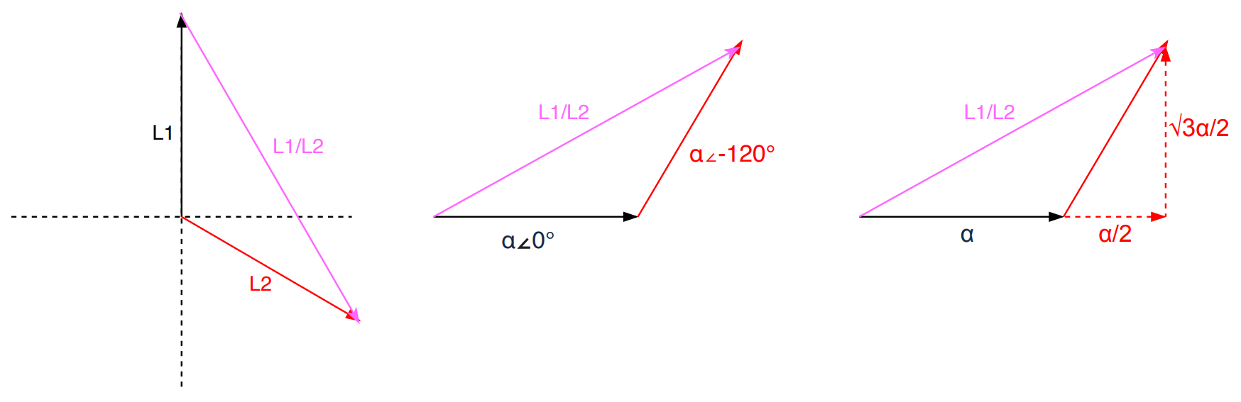
$$\text{L1/L2} = α∠\text{0°} - α∠\text{-120°}$$
$$\text{L1/L2} = (α\cos{\text{0°}}+jα\sin{\text{0°}})-(α\cos{\text{-120°}}+jα\sin{\text{-120°}})$$
$$\text{L1/L2} = (α\cos{\text{0°}}-α\cos{\text{-120°}})+j(α\sin{\text{0°}}-α\sin{\text{-120°}})$$
$$\text{L1/L2} = \frac{3}{2}α+j\frac{\sqrt3}{2}α$$
Convert L1/L2 into polar form:
$$\text{L1/L2} = \sqrt{(\frac{3}{2}α)^2 + (\frac{\sqrt3}{2}α)2}∠\tan{-1}(\frac{\frac{\sqrt3}{2}α}{\frac{3}{2}α})$$
$$\text{L1/L2} = \sqrt 3α∠\text{30°}$$
Since voltage is a scalar, we’re only interested in the “work”:
|L1/L2| = √3α
Given that α also applies for L3. This means for any of the three line pairs, we multiply the phase voltage by √3 to calculate the line voltage.
Vline = √3 x Vphase
Now with the three line powers being equal, we can add them all to get the overall effective power. The derivation below works for both Delta and Wye circuits.
Poverall = 3 x Pline
Poverall = 3 x (Vline x Iline)
Poverall = (3/√3) x (Vphase x Iphase)
Poverall = √3 x Vphase x Iphase
Using the US example, Vphase is 208V and Iphase is 24A. This leads to the overall 3-phase power to be 8646W (√3 x 208V x 24A) or 8.6kW. There lies the biggest advantage for using 3-phase systems. Adding 2 sets of coils and wires (ignoring the neutral wire), we’ve turned a generator that can produce √3 or 1.7 times more power!
Dealing with 3-phase
The derivation in the section above assumes that the magnitude at all three phases is equal, but we know in practice that's not always the case. In fact, it's barely ever. We rarely have servers and switches evenly distributed across all three branches on a PDU. Each machine may have different loads and different specs, so power could be wildly different, potentially causing a dramatic phase imbalance. Having a heavily imbalanced setup could potentially hinder the PDU's available capacity.
A perfectly balanced and fully utilized PDU at 8.6kW means that each of its three branches has 2.88kW of power consumed by machines. Laid out simply, it's spread 2.88 + 2.88 + 2.88. This is the best case scenario. If we were to take 1kW worth of machines out of one branch, spreading power to 2.88 + 1.88 + 2.88. Imbalance is introduced, the PDU is underutilized, but we're fine. However, if we were to put back that 1kW into another branch — like 3.88 + 1.88 + 2.88 — the PDU is over capacity, even though the sum is still 8.6kW. In fact, it would be over capacity even if you just added 500W instead of 1kW on the wrong branch, thus reaching 3.18 + 1.88 + 2.88 (8.1kW).
That's because a 8.6kW PDU is spec'd to have a maximum of 24A for each phase current. Overloading one of the branches can force phase currents to go over 24A. Theoretically, we can reach the PDU’s capacity by loading one branch until its current reaches 24A and leave the other two branches unused. That’ll render it into a 1-phase PDU, losing the benefit of the √3 multiplier. In reality, the branch would have fuses rated less than 24A (usually 20A) to ensure we won't reach that high and cause overcurrent issues. Therefore the same 8.6kW PDU would have one of its branches tripped at 4.2kW (208V x 20A).
Loading up one branch is the easiest way to overload the PDU. Being heavily imbalanced significantly lowers PDU capacity and increases risk of failure. To help minimize that, we must:
- Ensure that total power consumption of all machines is under the PDU's max power capacity
- Try to be as phase-balanced as possible by spreading cabling evenly across the three branches
- Ensure that the sum of phase currents from powered machines at each branch is under the fuse rating at the circuit breaker.
This spreadsheet from Raritan is very useful when designing racks.
For the sake of simplicity, let's ignore other machines like switches. Our latest 2U4N servers are rated at 1800W. That means we can only fit a maximum of four of these 2U4N chassis (8600W / 1800W = 4.7 chassis). Rounding them up to 5 would reach a total rack level power consumption of 9kW, so that's a no-no.
Splitting 4 chassis into 3 branches evenly is impossible, and will force us to have one of the branches to have 2 chassis. That would lead to a non-ideal phase balancing:
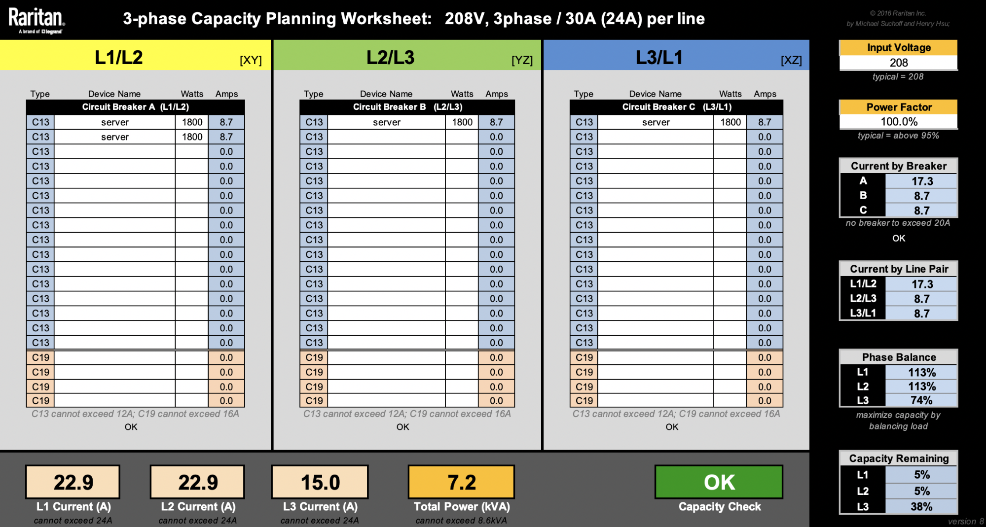
Keeping phase currents under 24A, there's only 1.1A (24A - 22.9A) to add on L1 or L2 before the PDU gets overloaded. Say we want to add as many machines as we can under the PDU’s power capacity. One solution is we can add up to 242W on the L1/L2 branch until both L1 and L2 currents reach their 24A limit.
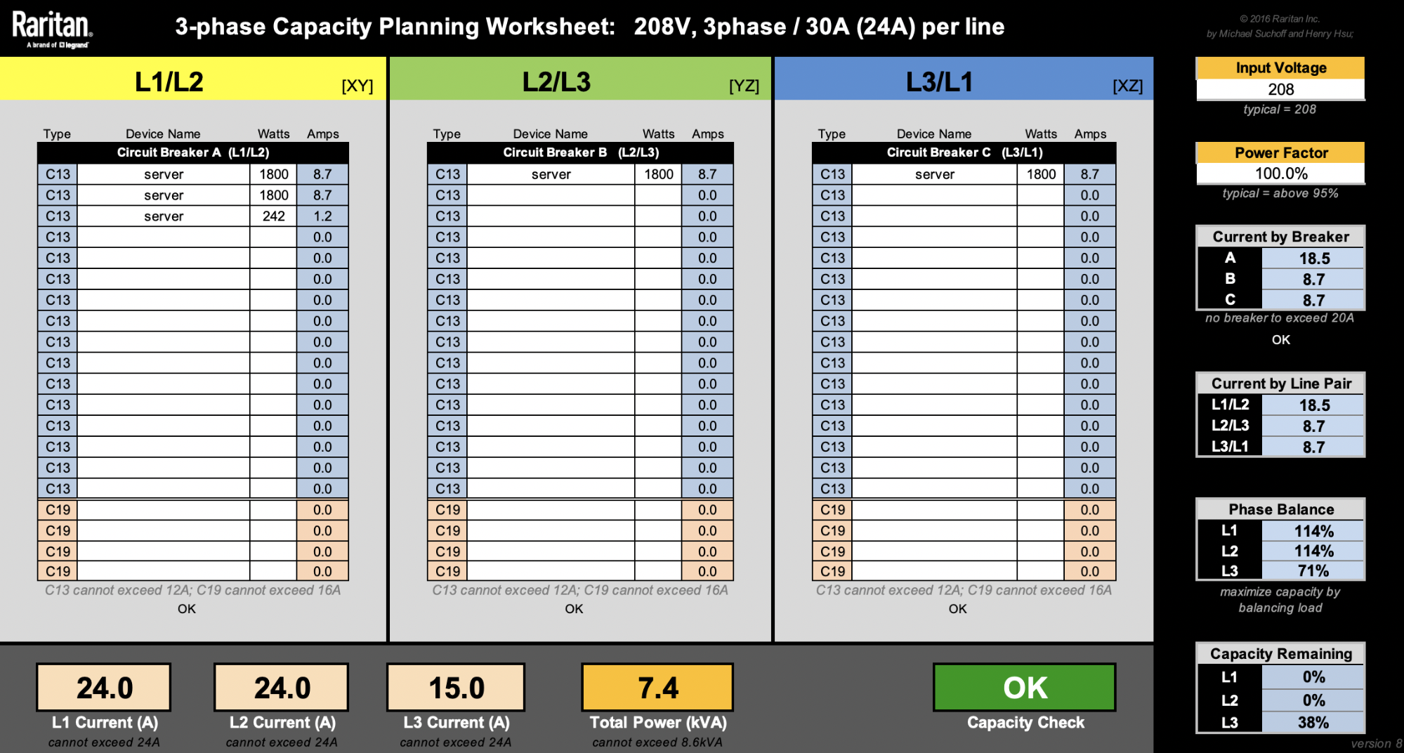
Alternatively, we can add up to 298W on the L2/L3 branch until L2 current reaches 24A. Note we can also add another 298W on the L3/L1 branch until L1 current reaches 24A.
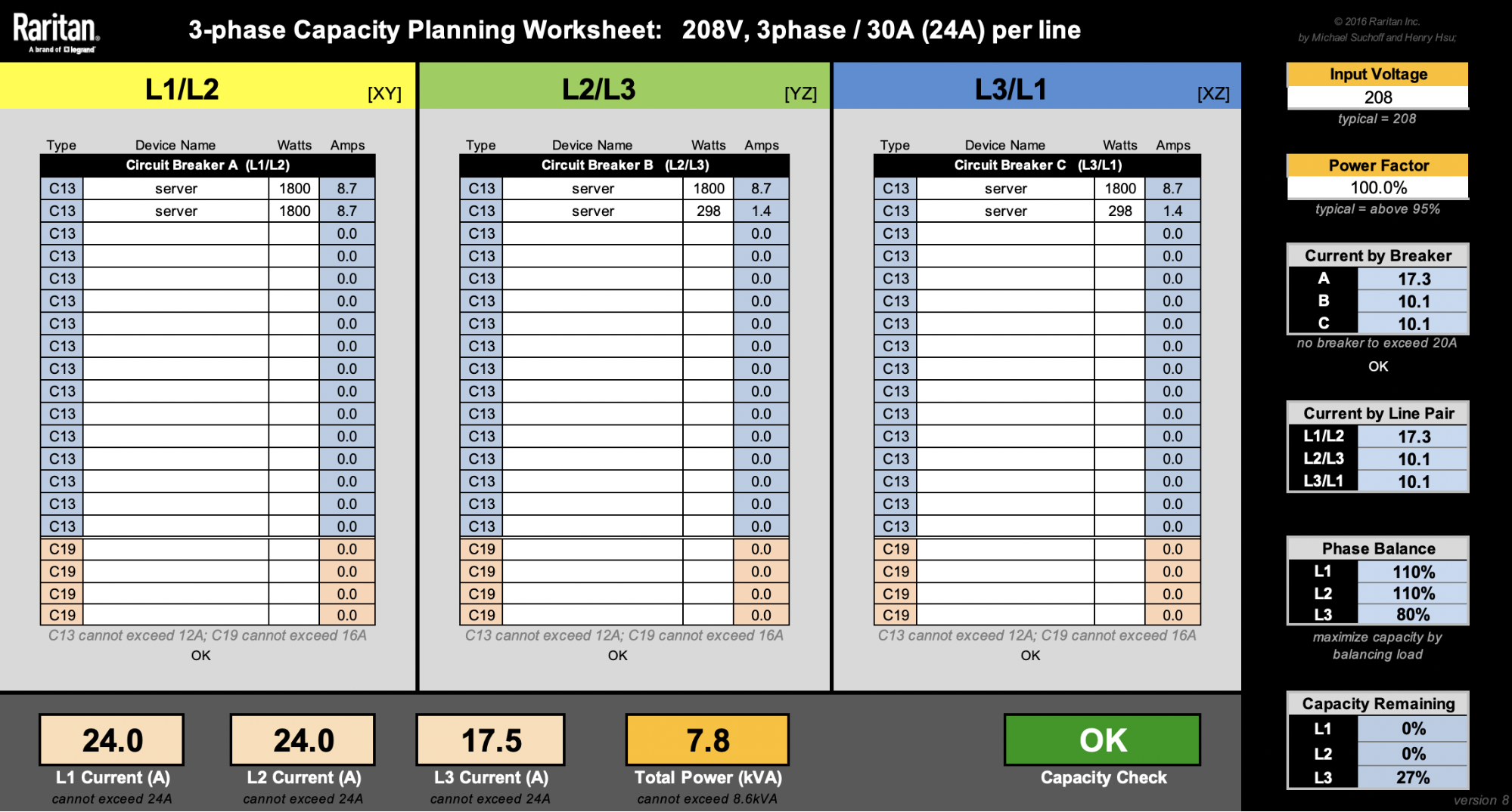
In the examples above, we can see that various solutions are possible. Adding two 298W machines each at L2/L3 and L3/L1 is the most phase balanced solution, given the parameters. Nonetheless, PDU capacity isn't optimized at 7.8kW.
Dealing with a 1800W server is not ideal, because whichever branch we choose to power one would significantly swing the phase balance unfavorably. Thankfully, our Gen X servers take up less space and are more power efficient. Smaller footprint allows us to have more flexibility and fine-grained control over our racks in many of our diverse data centers. Assuming each 1U server is 450W, as if we physically split the 1800W 2U4N into fours each with their own power supplies, we're now able to fit 18 nodes. That's 2 more nodes than the four 2U4N setup:
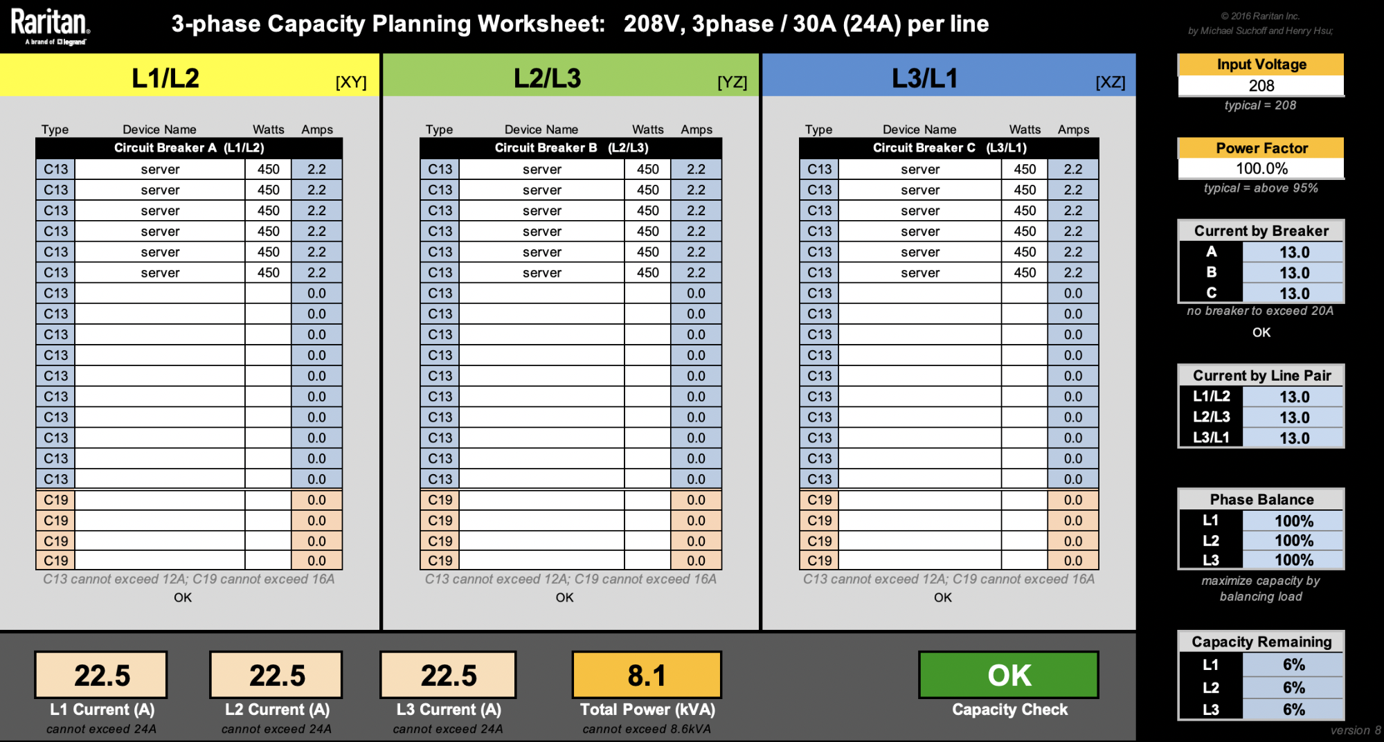
Adding two more servers here means we've increased our value by 12.5%. While there are more factors not considered here to calculate the Total Cost of Ownership, this is still a great way to show we can be smarter with asset costs.
Cloudflare provides the back-end services so that our customers can enjoy the performance, reliability, security, and global scale of our edge network. Meanwhile, we manage all of our hardware in over 100 countries with various power standards and compliances, and ensure that our physical infrastructure is as reliable as it can be.
There’s no Cloudflare without hardware, and there’s no Cloudflare without power. Want to know more? Watch this Cloudflare TV segment about power: https://cloudflare.tv/event/7E359EDpCZ6mHahMYjEgQl.